
Introduction
This is an open source project to connect a high durability yet inexpensive 8 opto-isolated input / 8 relay output WiFi and Ethernet enabled controller via an encrypted websocket connection to the Internet. The configuration features an extremely low latency command and control architecture using Nginx or Redis based pub-sub. The result is a high quality yet extremely low cost solution with a huge number of IoT applications such as: simple on/off control, one-shot activation of devices like garage doors, state monitoring, Internet home thermostat, burglar alarm, and sprinkler system control to name only a few. The goal is to create an open source ecosystem of inexpensive commodity hardware and application software for a wide range of IoT command and control applications.
Physical Inspection
The device used in this project is available from AliExpress for approximately $57 at the time of this writing.
Update 9/16/2016: This article appears to have sold out the original inventory on this item.
- Alternate Source: AliExpress $120
- Alternate Source: 16 Relay Version, no enclosure: AliExpress $44.99
- Alternate Source: Looks like it could be the same?: AliExpress $84.10
It comes with no useful documentation and its factory configuration is of limited value. There is no model number, so I decided to call it the A140808 which encodes the fact that it was the first project device (A) that I bought in 2014 and it has 08 inputs and 08 outputs.
 |
| Figure 1: The A140808 Device Enclosure with WiFi Antenna |
Upon examination of the outside of the device, the first clues that the device is built for industrial automation emerge. The first thing to note is that it supports a wide range of voltages from 7v to 28v (Figure 1) which is common for industrial automation equipment. Notice it does not specify AC or DC (examination of the buck converter later on shows that it is DC only).
The back of the enclosure (Figure 2) reveals more signs of its industrial automation purpose with the EN 50022 DIN mounting hardware.
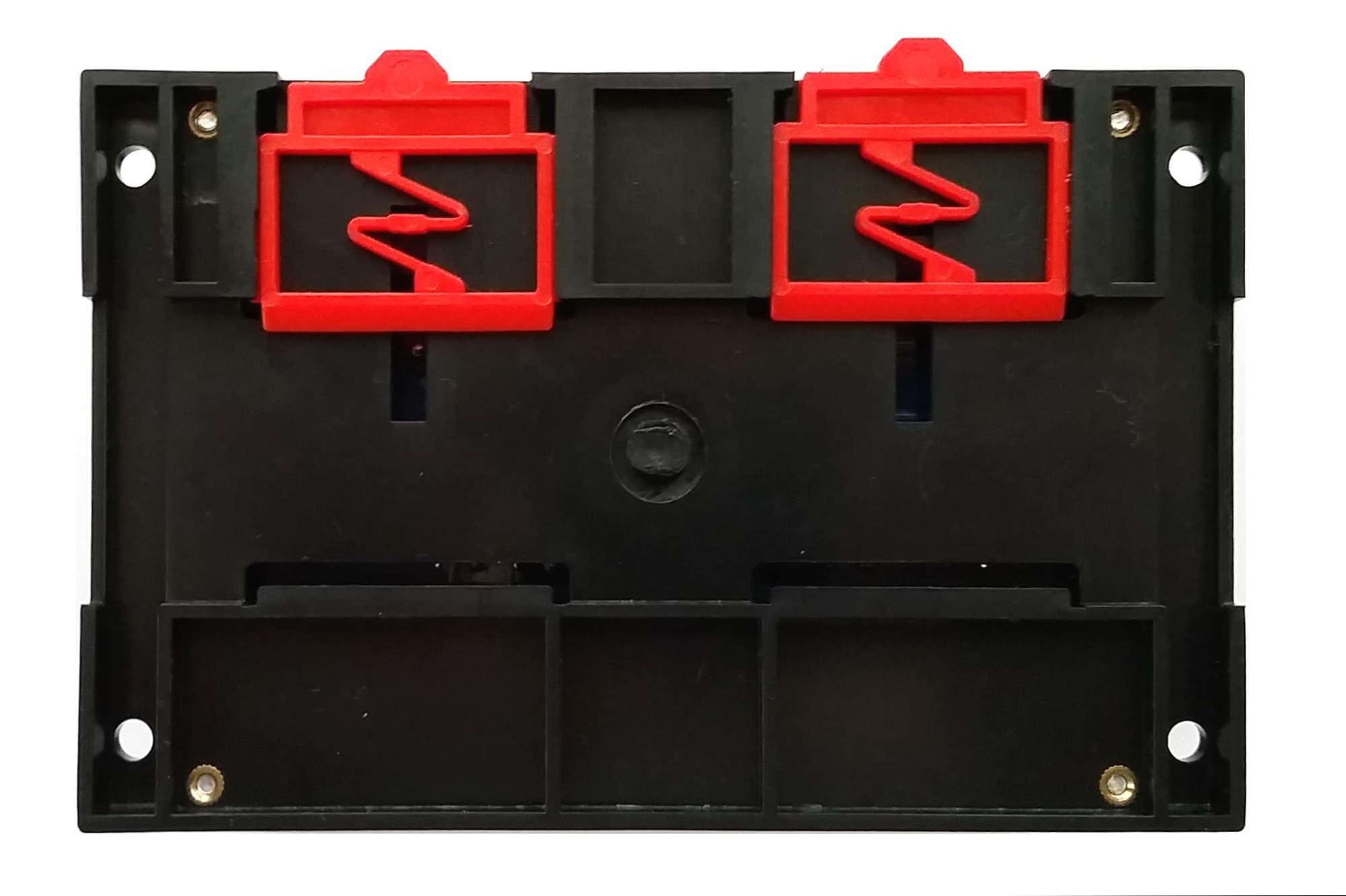 |
| Figure 2: The A140808 DIN Mounting Clips |
Teardown
Removing the cover of the A140808 reveals two major components (Figure 3). The first is the main IO board sporting an Atmel ATmega32A microcontroller (Figure 4). The ATmega32A is used to monitor the 8 opto-isolated inputs and to control the 8 relay outputs. The second major component is the Hi-Link HLK-RM04 Ethernet/WiFi/Serial module which runs embedded Linux (Figure 3, Figure 5). The microcontroller for the HLK-RM04 is a Ralink RT5350 SOC clocked at 360MHz. Ralink was purchased by MediaTek in 2011 and documentation for the SOC became very difficult to find for some reason. Fortunately, Michel Stempin and Jiapeng Li have created OpenWRT support for HLK-RM04 module which is based on the RT5350 SoC.
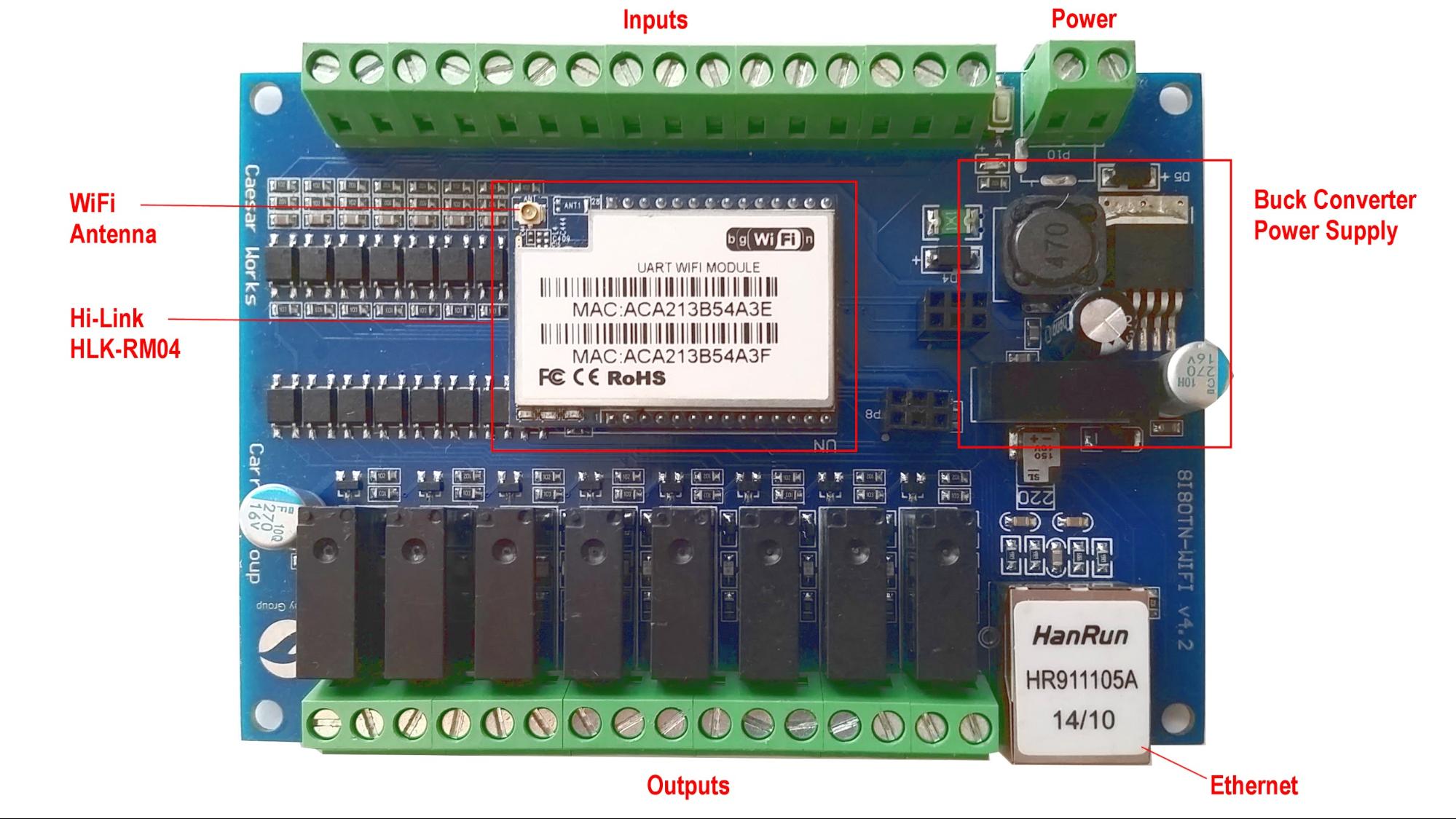 |
| Figure 3: Components of the A140808 |
Removing the socketed HLK-RM04 reveals the Atmel ATmega32A microcontroller (Figure 4). Note that the microcontroller also has a six pin ICSP programming header for our convenience. Unfortunately the header pinout is NOT AVR-ICSP compatible, so we will be building a custom wiring harness later on. It is also worth noting that the ATmega32A is very similar to the ATmega328P used on the Arduino UNO and the ATmega32U4 used on the Arduino Leonardo. We will be using the Arduino SDK to program this chip later on.
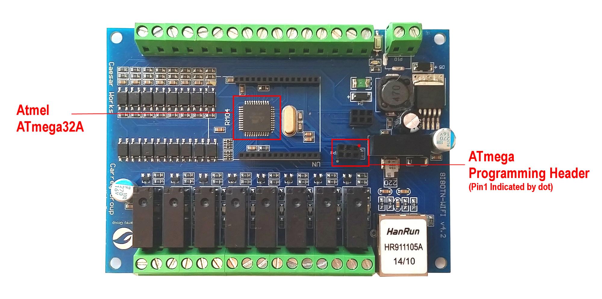 |
| Figure 4: Atmel ATmega32A and Six Pin Programming Header |
Looking at what all is included in this commercial quality device with WiFi, Ethernet, Ralink RT5350 SOC, Atmel ATmega32A, 8 opto-isolated inputs, 8 relay outputs, screw terminal connectors, DIN mounts, and a wide input voltage range of 7-28VDC, the A140808 is an incredible platform for open source IoT projects. Let’s get started converting this humble serial wifi relay into a full-fledged SSL websocket client of an Amazon Web Service based pub-sub service!
Getting Started
Linux Build Environment
The makefiles and shell scripts for this project are written for Linux. If you are not already setup to use Linux, the easiest way to do so is to either use VirtualBox with Vagrant or use the Amazon AWS Free Tier to build this project. Linux distributions such as Debian, Ubuntu, RedHat, CentOS, and Amazon Linux are all excellent choices and each are similarly easy to use for this project. It is beyond the scope of this document to provide information on setting up or using Linux. If you are unfamiliar with Linux, it is best to get a friend to help you out or read one of the excellent tutorials found online.
Ubuntu Trusty 14.04 requires the following prerequisites:
$ sudo apt-get update && sudo apt-get upgrade
$ sudo apt-get install make gcc g++ zlib1g-dev libssl-dev libncurses5-dev unzip pv git subversion docker.io
$ sudo usermod -G docker $USER
$ newgrp docker
Amazon Linux requires the following prerequisites:
$ sudo yum update
$ sudo yum install gcc gcc-c++ zlib-devel zlib-static openssl-devel ncurses-devel pv patch perl\(Thread::Queue\) perl\(Data::Dumper\) git subversion docker
$ sudo service docker start
$ sudo usermod -G docker $USER
$ newgrp docker
Security First
Comprehensive security is a primary concern of high quality IoT applications. This project utilizes well established RSA asymmetric encryption deployed with high strength 4096 bit keys. Additionally, the signed URL design combines HMAC hashing using the high security SHA256 algorithm (HMAC-SHA256) and are narrowly limited in time. In the near future, the signed URL implementation will also add adaptive complexity and salting similar to that which is found in the bcrypt key derivation function implementation.
The first step is to generate a self-signed Certificate Authority (CA) which will be built into the A140808 client device, smart phone client devices, as well as the server. This approach allows us to sign our own certificates and establish a tight client-server security contract extremely resistant to man-in-the-middle-attacks. Not only is this approach free, if properly deployed, it can be more secure than using a 3rd party CA that is susceptible to hacking, improper management, or poor judgment. However, it is important to note that the certificate strategy does not preclude the use of certificates signed by well-known CAs.
Generate the Certificate Authority
If you are comfortable generating your own self-signed CA and a certificate signed by this CA, do so now. Alternatively, you can use the two helper scripts gen_ca.sh and gen_cert.sh to simplify this process. Begin by downloading the scripts to a Linux machine:
$ wget -O certs.tar.gz https://github.com/rest-switch/stuff/archive/master.tar.gz
$ tar xzvf certs.tar.gz
$ cd stuff-master/certs
Generate the self-signed CA by specifying the CA organization name. The script will default to a key length setting of 4096 bits and a 10 year expiration. Use the –help command line switch to view the syntax for overriding these default options.
$ ./gen_ca.sh "Acme Co"When the script completes, it will emit the name of the public and private CA keys that were generated. This CA will be used to sign the certificate in the next step.
--> generated ca public cert:  acme-co_ca_public.cer
--> generated ca private key:  acme-co_ca_private
Generate and Sign the Certificate
The certificate that will be used to encrypt the websocket and https traffic to the web server requires specific information. It is not necessary to generate the certificate public / private key pair at this time, but if the web server domain name(s) are known, it is a convenient time to do so now using the gen_cert.sh script.
For example, to connect to the server using example.com, ws.example.com, and www.example.com, use the following syntax (see the –help command line switch to view all of the command line options):
$ ./gen_cert.sh -o "Acme Co" -d example.com -a "example.com ws.example.com www.example.com" -c "San Diego" -s CA -u acme-co_ca_public.cer -v acme-co_ca_privateWhen the script completes, it will emit the name of the public and private keys that were generated. For convenience, the script also emits a combined public certificate / CA chain file suitable for use with Nginx:
--> generated cert public cert:  acme-co_cert_public.cer
--> generated cert public cert chain:  acme-co_cert_chain_public.cer
--> generated cert private key:  acme-co_cert_private
The certificates needed for the entire project are now generated. It is easy to come back and generate new certificates as needed. It should also be noted that the A140808 device is setup to use multiple CAs and more than one can be generated at this point if so desired.
In the next step, the A140808 device image will be built and the public CA file(s) generated in this step will become part of the device firmware image itself. The details are provided in the next section, but for reference the firmware root CA staging directory is:
device_a140808-master/hlk-rm04/ca_certs
Certificate Review
In summary, the following certificate files and their use are as follows:
--> generated ca public cert: acme-co_ca_public.cerThe public certificate for the CA. This is used to validate the identity of subordinate certificates in the trust chain. In the case of this project both the A140808 device and the web server need to have access to a genuine copy of this certificate file.
--> generated ca private key: acme-co_ca_privateThe private certificate for the CA. This certificate is only used to sign certificate signing requests (CSRs). The privacy of this key is paramount to the integrity of the entire certificate trust chain and should be securely stored using best practices.
--> generated cert public cert: acme-co_cert_public.cerThis is the main public certificate is used to encrypt data between the client and the server. Clients need to trust the CA that signed this certificate or trust the certificate itself if it is a self-signed certificate.
--> generated cert public cert chain: acme-co_cert_chain_public.cerThis file is a combination of the public certificate and the public root CA certificates suitable for loading in Nginx. The point of this file is to be able to supply the non-well-known public certificate trust chain to clients at connect time.
--> generated cert private key: acme-co_cert_privateThe private certificate key for decrypting SSL communication at the server. This file must be present and kept secret on the web server.
Make a note of where these files are located as they will be used in the next steps to build the A140808 firmware and will be deployed with the Nginx web server Docker container.
Building the Firmware
Project Repository
Download the A140808 github repository and extract it:
$ wget -O device_a140808.tar.gz https://github.com/rest-switch/device_a140808/archive/master.tar.gz
$ tar xzvf device_a140808.tar.gz
$ cd device_a140808-master
The repository contains two subdirectories. The avr directory contains the complete project for building the firmware for the Atmel ATmega32A. Likewise, the hlk-rm04 directory contains the complete project for building the firmware for the Hi-Link HLK-RM04 module.
[device_a140808-master]$ ls -al
drwxrwxr-x 3 ec2-user ec2-user 4096 Oct  8 14:26 avr
drwxrwxr-x 5 ec2-user ec2-user 4096 Oct  8 14:26 hlk-rm04
-rw-rw-r-- 1 ec2-user ec2-user 1016 Oct  8 14:26 Makefile
-rw-rw-r-- 1 ec2-user ec2-user 1200 Oct  8 14:26 README.md
Executing make in the device_a140808-master directory will build both projects, or you can descend into either directory and execute make to build that project alone.
Building the Atmel ATmega32A Firmware
Switch to the device_a140808-master/avr directory and type make. The build will complete very quickly and the target binaries will be placed into the bin directory. The files of interest are a140808.hex or a140808.bin depending on the programmer used to flash the device.
[avr]$ ls -al bin
-rwxrwxr-x 1 ec2-user ec2-user  32768 Oct 23 19:14 a140808.bin
-rw-rw-r-- 1 ec2-user ec2-user     13 Oct 23 19:14 a140808.eep
-rwxrwxr-x 1 ec2-user ec2-user  51387 Oct 23 19:14 a140808.elf
-rw-rw-r-- 1 ec2-user ec2-user  14999 Oct 23 19:14 a140808.hex
-rw-rw-r-- 1 ec2-user ec2-user 141167 Oct 23 19:14 a140808.lss
-rw-rw-r-- 1 ec2-user ec2-user  34626 Oct 23 19:14 a140808.map
-rw-rw-r-- 1 ec2-user ec2-user  36320 Oct 23 19:14 avr_impl.o
-rw-rw-r-- 1 ec2-user ec2-user   2825 Oct 23 19:14 avr_impl.o.dep
-rw-rw-r-- 1 ec2-user ec2-user  41412 Oct 23 19:14 avr_main.o
-rw-rw-r-- 1 ec2-user ec2-user   2996 Oct 23 19:14 avr_main.o.dep
-rw-rw-r-- 1 ec2-user ec2-user     55 Oct 23 19:14 fuses.conf
-rw-rw-r-- 1 ec2-user ec2-user  26808 Oct 23 19:14 serial.o
-rw-rw-r-- 1 ec2-user ec2-user   2452 Oct 23 19:14 serial.o.dep
In a subsequent section, the source files and theory of operation will be discussed in greater detail. However, at this point this is all that is needed to be able to flash the ATmega32A device. Building the HLK-RM04 device is up next.
Building the Atmel HLK-RM04 Firmware
The Hi-Link HLK-RM04 module runs OpenWRT Linux. Additional information on OpenWRT and the Hi-Link device can be found on the OpenWRT wiki. Before building the firmware, the CA certificates build previously need to be copied to the project directory to be included in the resulting firmware image. Change to the device_a140808-master/hlk-rm04 directory and list the files.
[hlk-rm04]$ ls -al
drwxrwxr-x  2 ec2-user ec2-user 4096 Oct 23 10:10 ca_certs
drwxrwxr-x  3 ec2-user ec2-user 4096 Oct 23 10:03 files
drwxrwxr-x  2 ec2-user ec2-user 4096 Oct 23 10:03 firmware
-rw-rw-r--  1 ec2-user ec2-user 8442 Oct 23 10:03 Makefile
drwxrwxr-x 15 ec2-user ec2-user 4096 Oct 23 12:18 openwrt-master
drwxrwxr-x  5 ec2-user ec2-user 4096 Oct 23 10:03 tools
Copy CA Public Certificates
Take note of the ca_certs directory which is the location where the CA certificate that were generated earlier belong. Note that the firmware image only requires the public CA file(s). The build script will copy all files ending in _ca_public.cer to the firmware image so following this naming convention is required.
SSH Access
Next, the type of SSH access for the device needs to be considered. It is also possible to configure no SSH access. Certificates based SSH authentication is considered more secure, but password based authentication is also available. It is possible to configure both types of authentication then lockout the password based authentication mechanism at a later time as well. There is no great way to recover access if the certificate is lost or the password is forgotten, so regaining access would require reflashing the firmware. This is an open source project, and OpenWRT does make provisions for password recovery, so this could make a nice enhancement to the project. In general, questions regarding the HLK-RM04 device can easily be researched on the OpenWRT website.
On the command line, include one or more of the options desired. For example, to compile with password access and have the build process prompt (pmt) for the password, type:
$ make sshpw=pmtTo configure a password directly (“mysecret” in this example) and to bundle a newly generated SSH cert file, type:
$ make sshpw=mysecret sshcert=genNote that some options are mutually exclusive with each other. The full listing of options is as follows:
no ssh access: ssh=none
no ssh password access: sshpw=none
ssh password access (prompt): sshpw=pmt
ssh password access: sshpw=<password>
no ssh certificate access: sshcert=none
ssh certificate access, create new cert: sshcert=gen
ssh certificate access, use existing cert: sshcert=<filespec>
Note: If the build fails early before the .config configuration file can be generated, it is possible to get stuck at the Linux kernel config (blue) menu. You should never see this menu in a normal build. If this happens run a make distclean and restart the build from scratch.
Tip: Long-running builds will fail if the terminal session gets disconnected. Launch the screen utility to allow the build to continue even of the terminal session becomes disconnected. If the terminal session does become detached, reconnect to the Linux host and execute screen -r to reattach to the running session.
After the build finishes successfully, the firmware file openwrt-ramips-rt305x-hlk-rm04-squashfs-sysupgrade.bin will be placed into the hlk-rm04/bin directory. For details on the sysupgrade.bin file, refer to the OpenWRT wiki. The sysupgrade file does not include a bootloader, so it can only be used to update an already running A140808 device. In a later section of this article, instructions for doing so are included. In the case of a new device, it is necessary to build a full firmware image which takes a few more steps.
Adding u-boot
In order to be able to flash the device using a flash programmer, a complete firmware image file is required. In this case, the u-boot that ships with the HLK-RM04 can be used in conjunction with the MAC addresses printed on the front of the device (Figure 5).
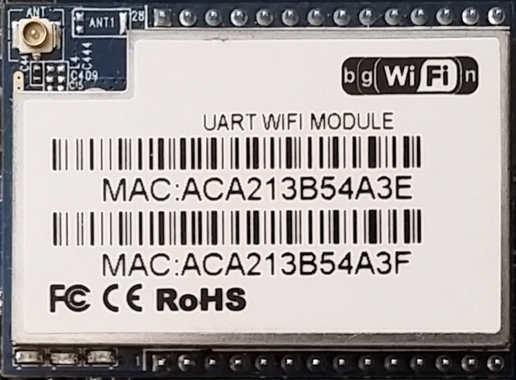 |
| Figure 5: The HLK-RM04 Module with MAC Addresses |
Notice that the MAC addresses are consecutive. To specify a MAC address and generate the full image firmware, use the make image mac=aabbccddeeff command and specify the first MAC address listed on your device (the build script will assume the second address). For example:
$ make image mac=aca213b54a3eThis will generate a full image firmware file with a unique serial number, for example:
hlk-rm04/bin/a140808_akbmkzh80.binThe serial number (aka Device Id) is a nine character alphanumeric code following the underscore. In the case above, the serial number is akbmkzh80. Each time a firmware is emitted, a unique serial number will be generated. Yours will be different than the one shown in this example. Record this number and affix it to the outside of the device; it will be used later to uniquely identify the device when it connects to the cloud.
The firmware generation for the HLK-RM04 is now complete. In the next section the firmware for the two chips will be written to their respective devices.
Flashing the Firmware
Programmers
The firmware for both the Atmel ATmega32A chip and the Hi-Link HLK-RM04 module need to be reflashed for this project. A very popular programmer for Atmel chips is the AVRISP mkII programmer. Flashing the firmware to the Atmel device is straightforward and can be done via the six pin programming header located on the circuit board (see Figure 4). Note that the pinout of the six pin programming header is different than the standard AVRISP pinout.
Programming the HLK-RM04 is more difficult. One approach involves replacing the u-boot bootloader and using TFTP to install OpenWRT via the serial console. This method is outlined in a separate article. Another more foolproof method is to use a chip programmer to write directly to the flash memory located on the bottom of the module. This article uses the Autoelectric MiniPro TL866A universal programmer and an 8 pin SOIC test clip. This technique is also agnostic to a bricked device and will always work in all circumstances.
An added bonus of the MiniPro TL866A model is that it has a six pin ICSP programming interface that can flash Atmel chips via the ICSP programming header located on the A140808 board (Figure 4). This makes it the only programmer needed for the entire project. Support for both the AVRISP mkII and the TL866A programmers are included in the supplied project makefiles.
Note: There are two models of the MiniPro TL866: The TL866A provides support for flashing Atmel chips via a six pin ICSP programming interface on the front. The less expensive TL866CS model does not include this ICSP interface and thus will require a second programmer for the Atmel device such as the AVRISP mkII.
AVRISP mkII Wiring Harness
The Atmel AVRISP mkII programmer pinout (Figure 6).
| 1 – MISO | 2 – VCC |
| 3 – SCK | 4 – MOSI |
| 5 – RESET | 6 – GND |
Figure 6: Atmel AVRISP Pinout
The proprietary A140808 ICSP programming header pinout (Figure 7).
| 1 – GND | 2 – VCC |
| 3 – RESET | 4 – MOSI |
| 5 – MISO | 6 – SCK |
Figure 7: A140808 AVR Programming Header Pinout
Programming the Atmel chip using the AVRISP mkII is very straightforward and easy to do. Ideally a custom male-male crossover cable would be built to remap the pins between the programmer and the A140808 programming header. However, since programming the A140808 is likely a one-time operation for most people, using jumper wires is going to make sense for most people. Both approaches are discussed below.
The custom male-male crossover cable approach uses standard female-female jumper wires and a standard six pin IDC female housings to yield the desired pin remappings. This creates a cable with two female ends. Next, the genders at each end are inverted using male-to-male IDC headers which can be super glued into the crossover cable IDC housings. Tip: A metallic silver Sharpie pen can be used to mark pin 1 on each end of the housing.
| DigiKey Part Number | Description |
| 929665-02-03-ND | 6 Pin Male-Male IDC Header |
| 952-2031-ND | 6 Pin Female Crimp IDC Housing |
| 1471-1230-ND | 150mm Female-Female Jumper Wire |
Table 1: Crossover Cable DigiKey Part Numbers
The completed conversion is shown in Figure 8. Notice that in this case heat shrink tubing has been used to secure the crossover cable to the programmer.
 |
| Figure 8: AVRISP mkII Programmer and Custom Crossover Cable |
Another approach is to use jumper wires for a one-time patch connection. It is worth noting that most off-the-shelf jumper wires are designed for use with breadboards and their pins are very narrow in diameter. The sockets of the female headers are designed to mate with square pin IDC type pins. Schmartboard Inc. makes jumper wires with these IDC square pin connectors. Schmartboard part number 920-0099-01 is a 10 pack of 7” jumpers that work very well in this application. This part can be sourced from Mouser Electronics.
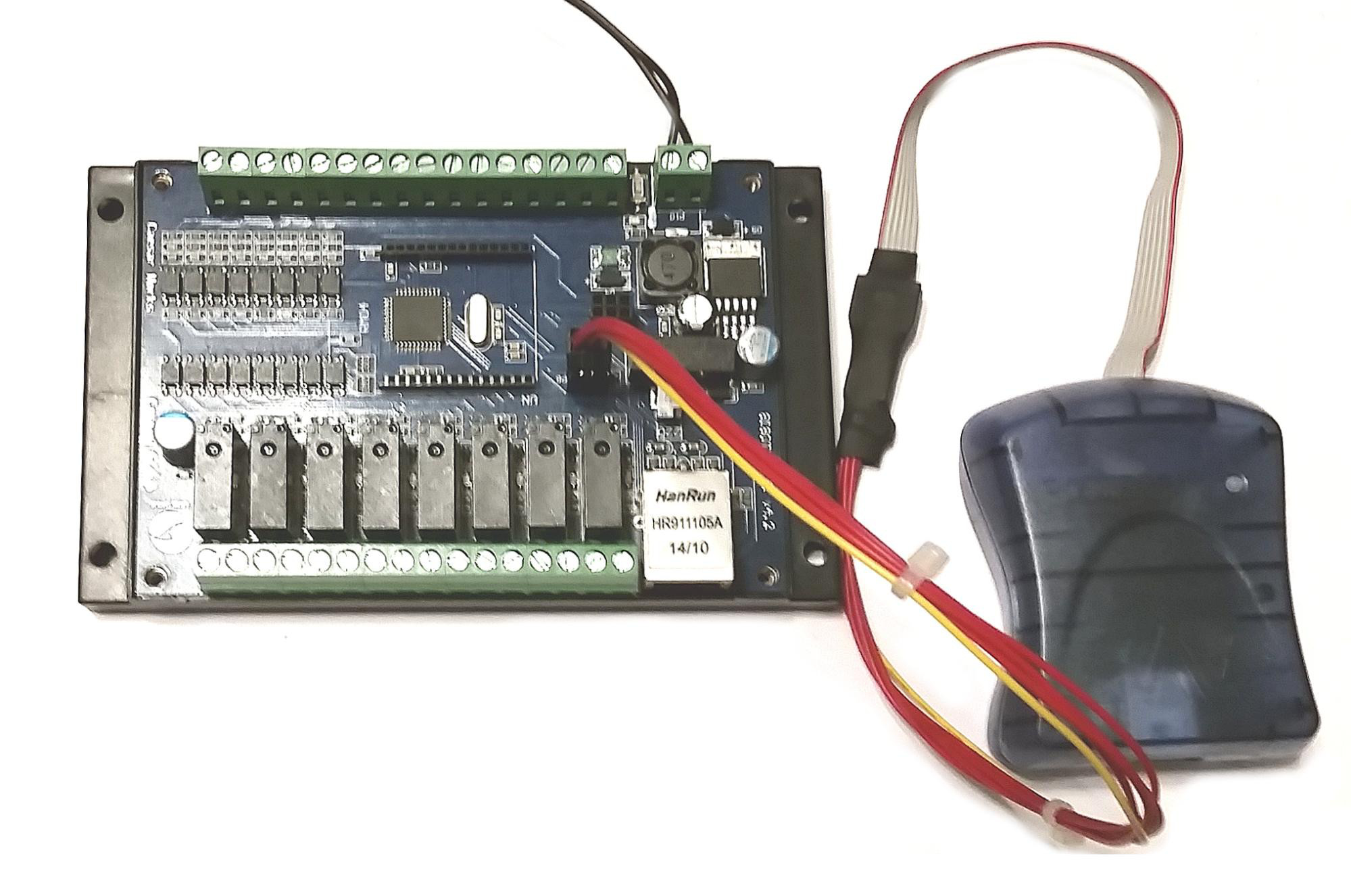
Autoelectric MiniPro TL866A Wiring Harness
The Autoelectric MiniPro TL866A programmer is two programmers in one. The TL866 “A” model has a six pin ICSP programming header that is very easy to reconfigure for programming the A140808. The pinout of the MiniPro ICSP interface (Figure 9) reveals that pins one and three are swapped between it and the A140808 device (compare with Figure 7). In this case, removing the connections from the MiniPro linear header and placing them in a 2x3 IDC housing (DigiKey 952-2031-ND) and changing the gender (DigiKey 929665-02-03-ND) is all that that is required.
| 1 – RESET | 2 – VCC | 3 – GND | 4 – MOSI | 5 – MISO | 6 – SCK |
Figure 9: MiniPro ICSP Pinout
The completed cable modification is shown in Figure 10.
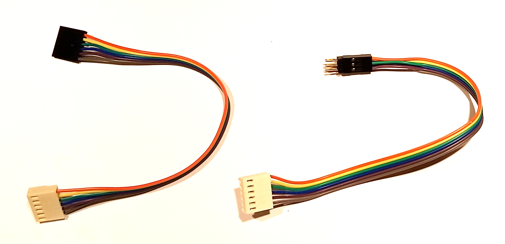 |
| Figure 10: MiniPro ICSP Cable (Left: Original, Right: Modified) |
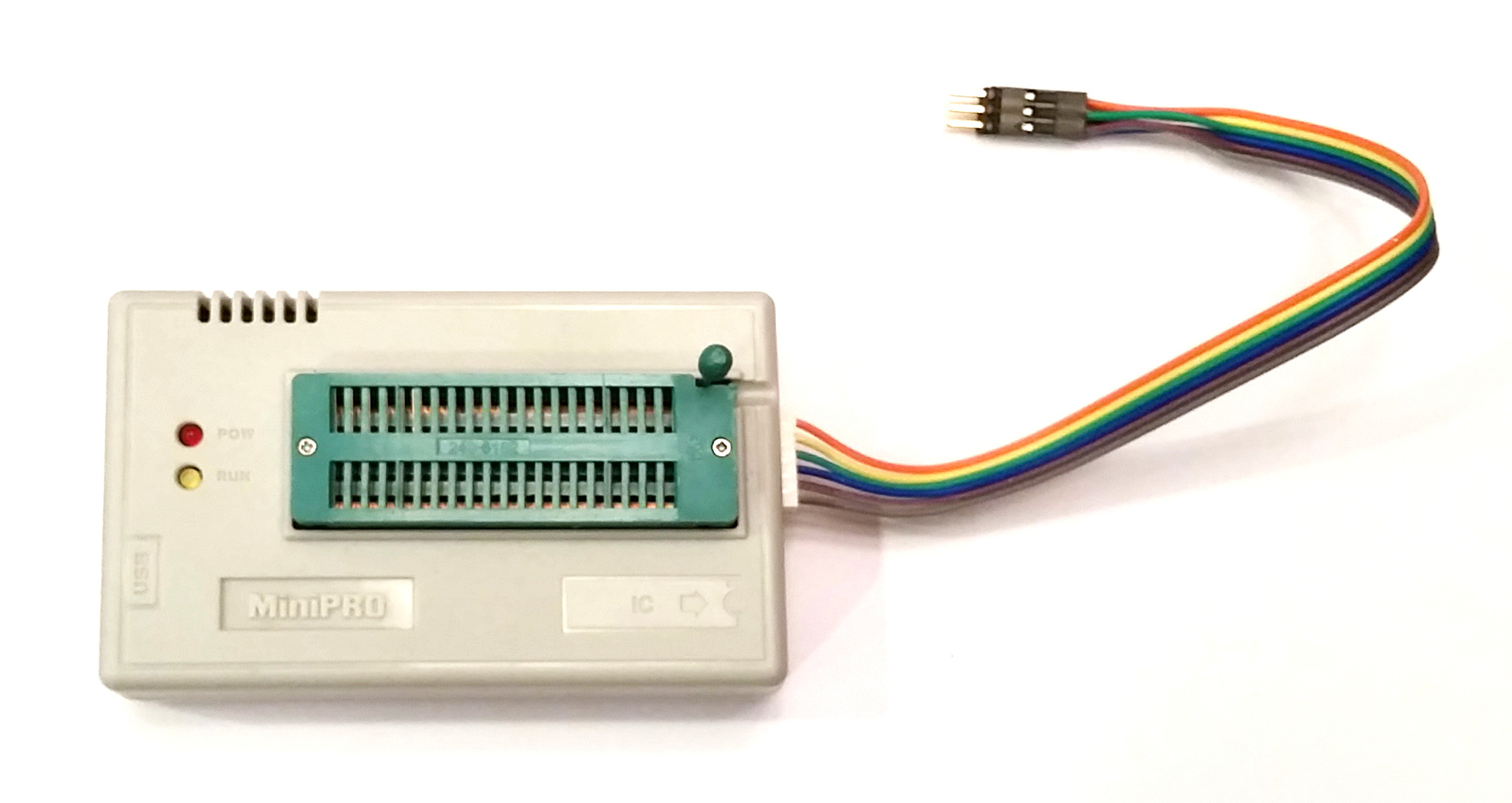 |
| Figure 11: MiniPro TL866A with Modified Six Pin ICSP |
USB Setup
A note about USB devices and Linux: To enable non-root access to the programmers in this article, a configuration file can be created defining the vendor and product ids for each device. To list devices connected to a Linux system, use the lsusb command.
Create a file named /etc/udev/rules.d/40-persistent-usb.rules and add the following entries to the file:
# autoelectric.cn minipro
SUBSYSTEM=="usb", ATTRS{idVendor}=="04d8", ATTRS{idProduct}=="e11c", MODE="0666", GROUP="plugdev"

# atmel avrisp-mkii
SUBSYSTEM=="usb", ATTRS{idVendor}=="03eb", ATTRS{idProduct}=="2104", MODE="0666", GROUP="plugdev"
Finally, add your user account to the plugdev group. It is necessary to log out and back in to pickup the rights from this new group membership.
sudo usermod -G plugdev $USER
Flashing the Atmel ATmega32A
Connect the desired Atmel programmer to the header closer to the relays taking care to orient pin 1 properly (see Figure 8). The A140808 device needs to be powered on via an external power source in order for programming to work. Once all connections are made and the device is powered on, use one of the following programming commands.
Note: The A140808 device must be powered on or programming will fail. Polarity for the device is indicated on the bottom of the board. If the barrel connector is present, the outside ring is negative.
To Select the AVRISP mkII:
$ cd device_a140808-master/avr
$ make avr-program
To Select the MiniPro TL866A:
$ cd device_a140808-master/avr
$ make mp-program
When the command finishes successfully, the Atmel programming is complete.
Flashing the Hi-Link HLK-RM04
The next step is to program the HLK-RM04. This step requires MiniPro TL866A and an 8 pin SOIC test clip. Start by identifying the flash memory on the HLK-RM04 device. The make and model of the flash memory are required when writing to the part. The part number is written on the chip itself. In my case the flash memory was covered with paint and required acetone and a cotton swab to remove. Using a smartphone to take a picture and zooming in, the part was identified as Winbond W25Q32BV. Other flash memory used by Hi-Link for the HLK-RM04 device include Macronix MX25L3206E and Chingis Pm25LQ032C. Undoubtedly Hi-Link uses other flash memories than the three listed here. This is an open source project, if your device has another type of flash memory, please create a pull request or submit a patch file.
Update: A Python script now exists to automate detection and programming.
To get a list of possible part numbers the MiniPro software can program, use the -l command line option (with a grep filter in this case):
If required, build the minipro binary first:
$ cd device_a140808/hlk-rm04
$ make minipro
Winbond W25Q32BV:
$ device_a140808-master/hlk-rm04/tools/minipro/minipro -l | grep W25Q32
W25Q32 @MLP8
W25Q32 @SOIC16
W25Q32BV
W25Q32BV @SOIC16
W25Q32BV @SOIC8
W25Q32BV @WSON8
W25Q32V @MLP8
W25Q32V @SOIC16
Macronix MX25L3206E:
$ device_a140808-master/hlk-rm04/tools/minipro/minipro -l | grep MX25L3206
MX25L3206E
MX25L3206E @SOP16
MX25L3206E @SOP8
MX25L3206E @USON8
MX25L3206E @WSON8
Multiple matching parts will likely be shown, but only the base part without the space will do the job. With the flash part number in-hand, it is time to proceed with programming. Clamp the test clip to the 8 pin flash memory module located on the bottom of the HLK-RM04 device taking care to orient pin 1 properly (see Figure 12).
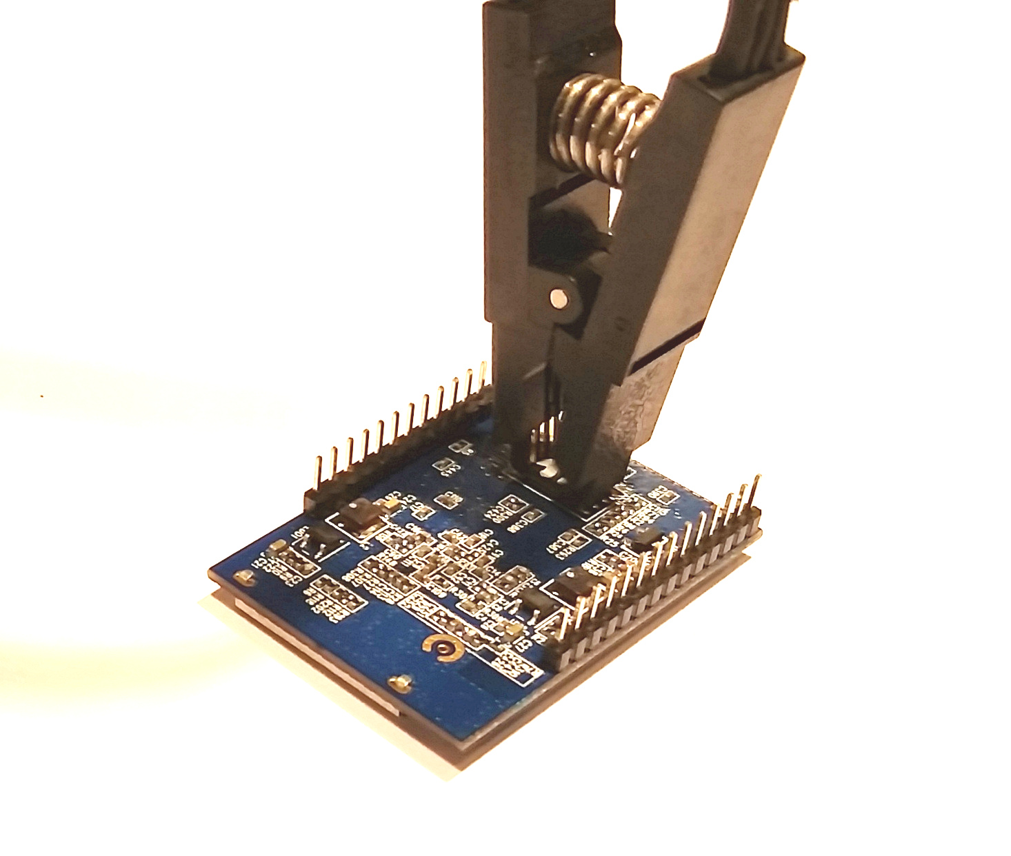 |
| Figure 12: SOIC Test Clip on Flash Memory Chip |
Once connected, the part is ready to program.
$ cd device_a140808-master/hlk-rm04
$ make program flash=W25Q32BV image=bin/a140808_akbmkzh80.bin
Note: The actual image= filename is build-specific and will be different than the one shown here.
Once the command successfully completes, the device is ready to boot. Insert the HLK-RM04 daughter card back into the A140808 main board. The pins are offset which prevents the device from being put in backwards, however, take care as to not misalign the pins along the socket.
Booting and SSH
Once powered on, the red LED light on the HLK-RM04 should begin to blink as Linux begins to boot. Once the kernel is loaded the network indicator lights will begin to flash. The device is setup to automatically accept a DHCP issued TCP/IP address, so it is a simple matter to scan the network to find it. Perhaps the easiest way to find the IP address associated with the MAC address used above (see Figure 5) is to search the logs of the network DHCP server. Other options include network scanning apps such as Fing for Android, LanScan for OSX, or nmap for Linux.
$ nmap -sP 192.168.1.0/24 >/dev/null && arp -an | grep -i ac:a2:13:b5:4a:3eOnce the A140808 IP address is determined, use ssh to login to the device for final configuration. To login, use root for the userid and the password or certificate used in the Building the Firmware step above.
$ ssh [email protected]
[email protected]'s password:


BusyBox v1.19.4 (2015-10-01 01:02:10 EDT) built-in shell (ash)
Enter 'help' for a list of built-in commands.

     ___  ___ ____ ___  ___  ___  ___
    / _ |<  // / // _ \( _ )/ _ \( _ )
   / __ |/ //_  _/ // / _  / // / _  |
  /_/ |_/_/  /_/ \___/\___/\___/\___/
                   powered by OpenWRT


root@a140808:~#
Building the Web Server
The web server used in this project is Nginx. The modular nature of Nginx lends itself well not only to serving html content, but it can also provide a rock-solid publish-subscribe facility through the use of the highly scalable and reliable push stream module by Wandenberg Peixoto. Other benefits of Nginx include extremely easy SSL setup and configuration as well as a wide range of other integration modules. While the overall solution was also demonstrated to very work well with both node.js and Redis, the simplicity and overall completeness of the Nginx solution edged out the competition for the goals of this application. The entire Nginx deployment package is bundled using a docker image which greatly simplifies numerous potential configuration and installation pitfalls making the entire process nearly foolproof.
To get started, we need to understand the mechanisms at play in the overall solution. When the A140808 client device boots up, a service starts on the device which attempts to establish an SSL websocket connection to a pub-sub host. The identity (host:port) of this cloud host is stored in the /etc/config/cloudcfg configuration file on the device. The SSL connection will be trusted as the public key of our own certificate authority (CA) was added to the /etc/ssl/certs directory when the device firmware was being built (see Security First). This design allows the device to become a command and control interface without any special firewall configuration, nor the need for any holes to be punched through the firewall. The result is a field configuration of the device that is no more difficult than establishing an ethernet connection and powering-on the device.
In addition to the pub-sub capability described above, the Nginx solution serves an html based control panel secured with auth basic over SSL. While it is possible to configure a database to handle more complex authentication scenarios and multi-tenant capabilities, such solutions will not be presented here for the sake of simplicity.
Begin by downloading the server_nginx repository and unpack:
$ wget -O server_nginx.tar.gz https://github.com/rest-switch/server_nginx/archive/master.tar.gz
$ tar xzvf server_nginx.tar.gz
$ cd server_nginx-master
The Docker directory contains all of the files needed to build the deployment package and the rs-docker-util.sh utility script used to help package and deploy the generated Docker container (more on the use of this script later).
[server_nginx-master]$ ls -al
drwxrwxr-x 3 johnc johnc 4.0K Sep 30 22:34 docker
-rw-rw-r-- 1 johnc johnc 6.3K Sep 30 22:34 Makefile
-rwxrwxr-x 1 johnc johnc 8.5K Sep 30 22:34 rs-docker-util.sh
Configuring Certificates
Before building the project, the public certificate chain (which is the public root CA and the public certificate together) need to be placed in the Docker directory along with the private key of the certificate as shown below. These certificates were created in the Security First section above. This example assumes these certs are stored in the home directory. Also note that the certificate names are being changed for the Docker script during the copy operation:
[server_nginx-master]$ cp ~/certs/acme-co_cert_chain_public.cer docker/cert-chain-public.pem
[server_nginx-master]$ cp ~/certs/acme-co_cert_private docker/cert-private.pem
Building the Docker Image
Once the certificates are in place, start building the Docker image by typing make. The build process begins by attempting to download the official CentOS 7 image for Docker (CentOS is debranded, free Red Hat Linux). After the image is downloaded, it is automatically updated via a yum update command then Nginx and its modules are built. In this case, the Nginx modules are the wandenberg pushstream module, and a custom sha256-hmac signed url authentication module which is used to authenticate requests from the web and Android clients.
The benefit of single-use signed-urls in this application is that they allow for simple one-shot messages to be passed in the clear without all of the setup overhead of an encrypted connection. Considering the latency of the mobile phone connection over a carrier or wifi network, shaving as many round-trips off really adds up quickly and provides for a more responsive user interface. More on this later.
If everything goes well, the build will complete after a few minutes:
. . .

Step 19 : CMD /usr/sbin/nginx
 ---> Using cache
 ---> 20c096a1a447
Successfully built 20c096a1a447

the docker image is now built
 - to run this image locally, run: "make run"
 - to run this image remotely, run: "make deploy"
At this point the Docker image is complete. Type make show to see result of the build process:
[server_nginx-master]$ make show

REPOSITORY                TAG       IMAGE ID       CREATED          VIRTUAL SIZE
restswitch/server_nginx   latest    8e2dd31572da   27 seconds ago   291.9 MB
restswitch/server_nginx   101       8e2dd31572da   27 seconds ago   291.9 MB
centos                    centos7   ce20c473cd8a   7 weeks ago      172.3 MB
--------------------------------------------------------------------------------
CONTAINER ID      IMAGE      COMMAND      CREATED      STATUS      PORTS      NAMES
If the build fails, it may be necessary to clean up partially built artifacts that were left behind. The make clean command attempts to do just this, but it cannot be too aggressive as other Docker images and containers may exist on the build system which do not belong to this build process. A more aggressive option is the make distclean command. If manual cleanup is required, the Docker image removal command is docker rmi <image id> and the Docker container removal command is docker rm <container id>. If you experience repeated build failures, try deploying an Amazon Linux AMI and build the image this way. Assuming all went well with the build, the image is ready to be run locally or packaged for deployment on a remote server.
Choose Docker HTTP Ports
The ports exposed from the Docker container can be remapped. The Nginx instance running within the container always uses the standard ports 80 for http and 443 for https. These ports can be mapped to any value by Docker when the container is created. These Docker port values can be changed by editing the Makefile or the rs-docker-util.sh file (depending on deploying locally or remotely).
EXPOSED_HTTP_PORT=80
EXPOSED_HTTPS_PORT=443
Packaging the Docker Image
To run locally, execute the make run command now and skip ahead to the Configure Passwords section below. Otherwise, to deploy to a remote server, the image must be packaged and deployed remotely. To package the image for remote deployment, use the make deploy command. The image deployment process will take a couple of minutes as the complete Linux filesystem is compressed into a tar archive:
[server_nginx-master]$ make deploy
deploying the latest docker image, please wait...
 289MiB 0:02:40 [1.81MiB/s] [=====================================================>] 100%
docker image packaging now complete: restswitch_web_docker_8e2dd31572da.tar.xz
use the rs-docker-util.sh script to help manage this image:
-rwxrwxr-x 1 ec2-user ec2-user 8644 Oct  1 02:34 rs-docker-util.sh
As indicated in the output message above, the deployment file in this case is restswitch_web_docker_8e2dd31572da.tar.xz This file ius used in conjunction with the rs-docker-util.sh file. These are the only two files needed to deploy the Docker image remotely. Copy both of these files to the remote server.
While waiting for the filesystem to compress, take a moment to see what all the rs-docker-util.sh script provides. Most of the commands found in the Makefile are duplicated in this script. This is so make is not required to be installed on the remote deployment machine. Use ./rs-docker-util.sh --help to display the command-line options:
[server_nginx-master]$ ./rs-docker-util.sh --help

Usage:
 rs-docker-util.sh <command>

Commands:
 clean                   remove everything but the restswitch_webserver docker image
 create [auto]           create [an autostart on boot] restswitch_webserver docker container
 debug                   enter a the running container or start a container using bash
 distclean               remove everything
 enter                   enter a running container (will autocreate and start if needed)
 load <tar.xz>           load an existing image
 run                     alias for start
 sethash <email> <pass>  set credentials for nginx.conf auth hash
 setpass <email> <pass>  set credentials for /secure website
 shell                   alias for enter
 show                    show docker image and container information
 start                   start restswitch_webserver docker container (will autocreate if needed)
 stop                    stop restswitch_webserver docker container
 term                    alias for enter
 terminal                alias for enter
 tidy                    similar to clean, but does not remove container
One command worth noting is the ./rs-docker-util.sh enter command. This command will run a bash shell in the running container allowing ssh-like access to the instance. This is handy for getting inside to review log files or to change configuration. Also notice the sethash and setpass commands: these command are used to configure Nginx settings without entering the container (more on this later).
After the restswitch_web_docker_8e2dd31572da.tar.xz and rs-docker-util.sh files have been copied to the remote deployment machine, create a Docker container from the compressed Docker image by typing: ./rs-docker-util.sh load restswitch_web_docker_8e2dd31572da.tar.xz
$ ./rs-docker-util.sh load restswitch_web_docker_8e2dd31572da.tar.xz
loading image: restswitch_web_docker_8e2dd31572da.tar.xz
please wait...

REPOSITORY                TAG      IMAGE ID       CREATED       VIRTUAL SIZE
restswitch/server_nginx   latest   8e2dd31572da   2 hours ago   291.9 MB
The image is now installed and ready to be launched in a new Docker container.
Creating and Running the Docker Container
The last step is to configure the userid and passwords used to secure the system. The system is secured via two different credential sets. The first credential set secures the web based control panel using standard auth-basic authentication over SSL. The second set of credentials are used to sign the single-use secure URLs clients will use to send commands to the system. It may seem a little confusing why two credential sets exist, but take a moment to understand them both. It is recommended to use an email address for the userid. Note that the userid need not be an email address, but each user of the system must use a unique userid. Using an email address for the userid ensures global uniqueness. Additionally, the UI for both the control panel web page and the Android client label this field as “email address” so it may reduce confusion down the road to use an email address now.
To assign the password used to secure the control panel web page, use the setpass command supplying the email address and password to be used: ./rs-docker-util.sh setpass "[email protected]" "my-secure-web-password"
Likewise, to assign the password that will be used for signed URLs, use the sethash command supplying the email address and password to be used. To set the signed url userid and password, type: ./rs-docker-util.sh sethash "[email protected]" "my-signed-url-password"
$ ./rs-docker-util.sh create
creating restswitch_webserver container...
7cd5b2c63c1649e99cc5b96df6cc0b254610866bac811408fde451b4d610788b

$ ./rs-docker-util.sh show
REPOSITORY                TAG      IMAGE ID       CREATED       VIRTUAL SIZE
restswitch/server_nginx   latest   8e2dd31572da   2 hours ago   291.9 MB
-------------------------------------------------------------------------------------------------------------------------
CONTAINER ID   IMAGE                            COMMAND             CREATED         STATUS   PORTS   NAMES
7cd5b2c63c16   restswitch/server_nginx:latest   "/usr/sbin/nginx"   6 seconds ago                    restswitch_webserver
The key thing to notice from the ./rs-docker-util.sh show output above is that the STATUS column above does not indicate a status of EXITED. A status of exited indicates a failure of Nginx to start. One reason Nginx will refuse to start is if missing or invalid SSL certificates were supplied in the Configuring Certificates step above. In order to make a better assessment of why Nginx is failing to start, it may be necessary to forcibly enter the Docker container and manually excute nginx at the command line. To start the Docker container forcibly, use the ./rs-docker-util.sh debug command.
If all went well and the container is now running, it is possible to enter the running container with the ./rs-docker-util.sh enter command. Type exit to leave the container when finished browsing around.
$ ./rs-docker-util.sh enter
[root@7cd5b2c63c16 /]# ls -al
total 48
lrwxrwxrwx   1 root root    7 Aug 14 21:00 bin -> usr/bin
drwxr-xr-x   5 root root  360 Nov  2 18:32 dev
drwxr-xr-x  48 root root 4096 Nov  2 17:54 etc
drwxr-xr-x   2 root root 4096 Jun 10  2014 home
lrwxrwxrwx   1 root root    7 Aug 14 21:00 lib -> usr/lib
lrwxrwxrwx   1 root root    9 Aug 14 21:00 lib64 -> usr/lib64
drwx------   2 root root 4096 Aug 14 21:00 lost+found
drwxr-xr-x   2 root root 4096 Jun 10  2014 media
drwxr-xr-x   2 root root 4096 Jun 10  2014 mnt
drwxr-xr-x   2 root root 4096 Jun 10  2014 opt
dr-xr-xr-x 113 root root    0 Nov  2 18:32 proc
dr-xr-x---   3 root root 4096 Nov  2 18:32 root
drwxr-xr-x   5 root root 4096 Nov  2 18:32 run
lrwxrwxrwx   1 root root    8 Aug 14 21:00 sbin -> usr/sbin
drwxr-xr-x   2 root root 4096 Jun 10  2014 srv
dr-xr-xr-x  13 root root    0 Nov  2 18:32 sys
drwxrwxrwt   7 root root 4096 Nov  2 18:34 tmp
drwxr-xr-x  13 root root 4096 Aug 14 21:00 usr
drwxr-xr-x  20 root root 4096 Nov  1 01:51 var

[root@7cd5b2c63c16 /]# exit
Configure Passwords
The last step is to configure the email and password used to secure the site. Using an email address for the userid ensures global uniqueness. To assign the password used to secure the control panel web page, use the setpass command supplying the email address and password to be used: ./rs-docker-util.sh setpass "[email protected]" "mysecret"
Tip: If the password contains any special characters like \ or & the BASH shell will try and interpret and consume these characters. It is always a good idea to quote protect passwords when passing on the command-line as shown above to prevent this from happening.
The system is now ready to be used. The control panel web page can be accessed via the /secure/ route: https://mydomain.com/secure/ Note that if a custom port (other than 443) was selected, it is necessary to supply it after the host with a colon: https://mydomain.com:8443/secure/ Also note that if a custom port is used, the trailing slash MUST be specified or the browser will attempt to 301 follow the URL using the default 443 port.
A140808 Device Setup
At this point we are ready to configure an A140808 device for use with the system and run an end-to-end test! The first thing to do is to set the host name and port of the web server on the A140808 device. Access the device using ssh (see Booting and SSH). Once connected, edit the /etc/config/cloudcfg file to set the host name and port (8443 in this example). The A140808 daemon will need to be restarted to pickup the new value.
$ echo '52.1.48.84:8443' > /etc/config/cloudcfg

$ /etc/init.d/a140808 restart
stopping deamon...
starting deamon...
child process pid: [783]

$ logread
 . . .
Nov  2 21:56:19 a140808 daemon.notice a140808[2014]: daemon started
Nov  2 21:56:19 a140808 daemon.notice a140808[2014]: opening /dev/ttyS1 at 57600 baud, E71
Nov  2 21:56:19 a140808 daemon.notice a140808[2014]: connecting to host: [52.1.48.84]
Nov  2 21:56:19 a140808 daemon.debug a140808[2014]: ws_connect
Nov  2 21:56:19 a140808 daemon.debug a140808[2014]: ws_connect: creating context
Nov  2 21:56:19 a140808 daemon.debug a140808[2014]: ws_connect: connect request succeeded
Nov  2 21:56:20 a140808 daemon.notice a140808[2014]: ws_onevent: LWS_CALLBACK_CLIENT_ESTABLISHED
Nov  2 21:56:20 a140808 daemon.info a140808[2014]: ws_onopen -- connection established --
Notice the last line in the log output. The “connection established” message indicates that everything went well. If the a140808 daemon is stuck in a reconnect loop instead, there is a very good chance the public root CA certificate is not properly installed on the device or the web server. This certificate should live in the /etc/ssl/certs directory on the A140808 device, and have a symbolic link named by taking the hash + .0 of the CA public certificate. To compute the hash of the public CA certificate, use a machine with openssl installed and issue the command openssl x509 -hash -noout -in <ca_filename.cer>
root@a140808:~# ls -al /etc/ssl/certs
drwxr-xr-x    1 root     root             0 Oct  3 23:43 ./
drwxr-xr-x    1 root     root             0 Oct  1 05:05 ../
lrwxrwxrwx    1 root     root            13 Oct  3 23:43 7543b2d6.0 -> acme-co_ca_public.cer
-rw-r--r--    1 root     root          2118 Oct  3 23:43 acme-co_ca_public.cer
Once the A140808 device is able to connect with the web server, check the /secure/stats endpoint to see the devices registered with it. The endpoint is secured by the userid (email) and password specified above in the setpass step. Issue the following command to see the devices registered with the server (note that you must specify the userid after the --user command line option):
$ wget --user <userid> --ask-password -qO- --no-check-certificate "https://52.1.48.84/secure/stats?id=ALL"
{ "hostname": "7cd5b2c63c16",
  "time": "2015-11-02T00:20:05",
  "channels": "1",
  "wildcard_channels": "0",
  "uptime": "20865",
  "infos": [{
    "channel": "akbmkzh80",
    "published_messages": "0",
    "stored_messages": "0",
    "subscribers": "1"
  }]
}
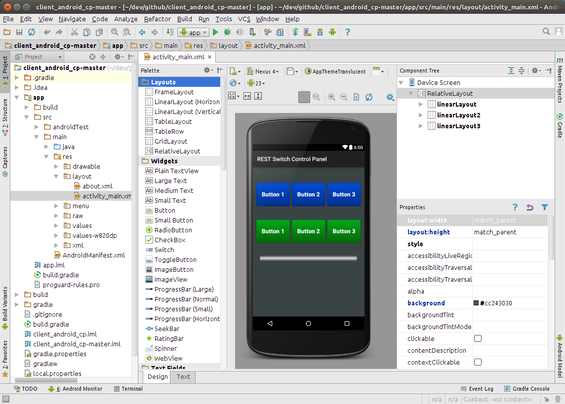
Configure Control Panel
Now that the A140808 device has a connection to the web server, it is now possible to issue a command to it. To issue a command, the web page control panel needs to be configured with the serial number (aka Device ID) of the device to control, in this case akbmkzh80 See Adding u-boot above for details on the device serial number. The other configuration task is to enter the email address and password that was set for the signed url hash above (see Configure Passwords).
The Device Control Panel web page has two device sections for controlling two different unique devices. Paste the serial number in the upper-right edit field where it says “Device ID” of either one.
Finally, in the upper-right corner of the web page, click the “Sign In” menu item, and enter the email address and password assigned previously (see sethash above), and then click the “Sign In” button.
At this point the configuration is complete! Clicking “Button 1” should result in relay 1 clicking shut for 250 ms. Likewise, clicking “Button 2” should result in relay 2 clicking shut for 250 ms. Now that the system is working end-to-end, it is time to build the Android client.
Building Android
The Android client implements equivalent functionality to that of the web control panel as a native Android app. The app is designed with a quick access and quick dismissing overlay style to make it as convenient as possible to popup and dismiss quickly. Android is the only mobile app available for this project right now, so an iOS port pull request would be greatly appreciated.
Installing Android Studio
The Android Studio IDE needs to be installed to complie and deploy the app. This overview is not meant to be a tutorial on how to get up an running with Android Studio, many great articles are available. I personally used the Android Studio Development Essentials eBook and got a lot out of it. Get started by downloading and installing the Oracle Java JDK 7 and then the Android Studio IDE.
Download Android Project Files
Once Android Studio has been installed, download the A140808 github repository and extract it:
$ wget -O client_android_cp.tar.gz https://github.com/rest-switch/client_android_cp/archive/master.tar.gz
$ tar xzvf client_android_cp.tar.gz
$ cd client_android_cp-master

[client_android_cp-master]$ ls -al
total 32K
drwxrwxr-x 3 johnc johnc 4.0K Oct  5 07:39 app
-rw-rw-r-- 1 johnc johnc 1.4K Oct  5 07:39 build.gradle
-rw-rw-r-- 1 johnc johnc 1.9K Oct  5 07:39 client_android_cp.iml
drwxrwxr-x 3 johnc johnc 4.0K Oct  5 07:39 gradle
-rw-rw-r-- 1 johnc johnc 1.8K Oct  5 07:39 gradle.properties
-rwxrwxr-x 1 johnc johnc 5.9K Oct  5 07:39 gradlew
-rw-rw-r-- 1 johnc johnc  925 Oct  5 07:39 settings.gradle
Using the Android Studio welcome dialog, select the “Open an existing Android Studio project” menu option and navigate to the client_android_cp-master directory. After a few moments the IDE should come up with the project loaded. Android Studio is extremely user friendly and it will prompt to download any missing components.
Build Android Project Files
Select “Build -> Make Project” from the menu to confirm the project builds successfully. There are not many options to tune in the app at compile time. Two settings which may be of interest for compile time tuning are located in the AjaxTask.java file: CONNECT_TIMEOUT_MS and READ_TIMEOUT_MS
The app can be tested from within Android Studio by selecting “Run -> Run ‘app’” from the menu. The “Device Chooser” dialog will appear where an Android device emulator may be selected. If an Android virtual device is not available from the dropdown, it may be necessary to create a new virtual device first. Another option is to use a physical Android device as the target device.
All relevant settings for connecting the app to the web server as well as device selection are set at runtime in from the app settings menu. Note that the raw password is not stored on the device and is HMAC hashed with the email address. Therefore, changing the email address invalidates the hash and the password will need to be reset afterward.
Once you are satisfied with the functioning of the app, a signed apk can be generated for deploying to a physical device by selecting “Build -> Generate Signed APK…” and following the prompts. After the signed apk has been generated, transfer the file to the phone. One way of transferring the apk file to the phone is via email.
Conclusion
The A140808 controller is a powerful, robust, and inexpensive platform. This article is mainly geared toward getting up and running. Later articles will dive deeper into the extensive facilities and command set of the device. For example, the outputs can be set on, off, or toggled for 0-255ms. Additionally, the inputs can be read or trigger a webhook. Digging into the device firmware source is a great place to start.
The A140808 platform has several potential applications:
Garage Door Opener
Thermostat
The potential exists for controlling an HVAC system much the same way the BayWeb Thermostat does. In this application a remote temperature sending device needs to be added either via serial (i.e. RS485) or WiFi connection. The number of relay outputs of the A140808 device are suitable and appropriate for controlling modern HVAC equipment.
Sprinkler System Control
The relay outputs of the A140808 device also make it highly siutable for controlling a sprinkler system the way other projects do, but at a much lower cost.
Home Alarm
Integration with an existing alarm system or alarm system components for an open source extensible alarm system.
Other Hardware
Other projects based on the Ralink RT5350 SOC include devices in the WeMo hardware line. Presumably, only minor modifications to this project would be needed to take advantage of this hardware.
How to Help
The goal of this effort is to create a highly secure open source IoT ecosystem. A primary problem with existing IoT products is weak security. Unfortunately high security and encryption create an opaque environment, and consumers have no good way of knowing what their IoT devices are doing. One way to remove this uncertainty is to open source the implementation.
The goal of the hardware is to adapt off-the-shelf hardware for IoT projects. The goal is not to create a fragile connection from a Raspberry Pi to a garage door. All projects must be safe and suitable to run in an industrial, commercial, or residential application.
This is an open source project and pull requests are greatly appreciated. This project is still in need of core committers, if you have an interest at this level, please contact me directly.